Calculation wizards
Basic principles regarding minimum distances (safety distances)
Electro-sensitive protective devices such as safety light curtains and safety laser scanners detect the approach of persons toward a point of operation. They do not prevent access to the point of operation, but from a sufficient distance from the point of operation they must cause the hazards to become ineffective in good time, e.g. cause movements to come to a standstill. The minimum distance is calculated in accordance with ISO 13855 as follows
SRT [mm] = K [mm/ms] * T [ms] + CRT [mm]
SRT – minimum distance between the protective field and point of operation [mm]
K – approach speed: access by upper limbs: 2.0 mm/ms / entry: 1.6 mm/ms
T – stop time of the safety function after entry of the relevant part of the body into the protective field [ms]
CRT – constant additional distance depending on the detection capability of the protective device [mm]
The minimum distance of electro-sensitive protective devices therefore consists of a constant (C) and a dynamic (K x T) component. As an electro-sensitive protective device too can be circumvented by reaching over, similar to guards the necessary height of the protective field must be determined from a table. The necessary distance to the point of operation therefore corresponds to the larger of the two values
- SRT (reach-through), calculated based on approach through the protective field
- SRO (reach-over), with CRO from the height of the top edge of the protective field and the height of the point of operation
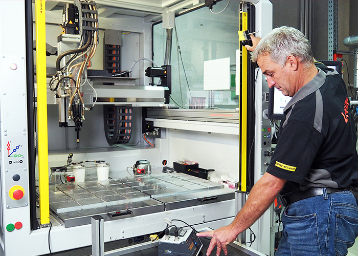
The total stop time T can only be determined with sufficient accuracy by means of measurement. Special stopping time measuring devices are used for this purpose. Measurement of the stopping time is a service offered by Leuze. According to legal requirements, a safety inspection which also includes the stopping time measurement may be performed only by competent persons.
Stopping time measurement service
Wizards for calculating the minimum distance (safety distance) in accordance with ISO standards
The recommendations of this wizard do not lay any claim to being complete. To ensure correct safety-related use and mounting of the products, it is essential to observe the latest version of the respective standards and regulations. Leuze electronic GmbH + Co. KG assumes no liability for damage resulting from the use of this wizard or for the accuracy of the generally applicable standards and directives.
Calculation of the minimum distance (safety distance) with perpendicular approach and a resolution of ≤ 40 mm (ISO 13855)
The minimum distance SRT is calculated using the following formula: SRT: Minimum distance between the protective field and point of operation |
Initially, the value of 2.0 mm/ms is used for K. If the calculation results in SRT > 500 mm, the calculation may be repeated with K = 1.6 mm/ms. The result for SRT must be at least 500 mm in the second step (if the calculated value is lower, SRT is set to 500 mm).
Attention: The distance S to the point of operation must always be at least 100 mm, even if a lower value was calculated.
Calculation of the minimum distance (safety distance) with perpendicular approach and a resolution of > 40 mm (ISO 13855)
Note: This formula applies to multiple light beam safety devices, safety light curtains and safety laser scanners with corresponding resolution.
The minimum distance SRT is calculated using the following formula: SRT: Minimum distance between the protective field and point of operation |
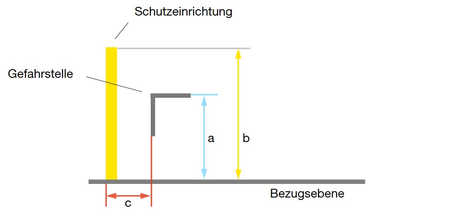
S: Minimum distance
a: Height of the bottom beam above the reference plane
b: Height of the top beam above the reference plane
Note: The table value for CRO (reach-over) must also be determined. This is usually greater than 850 mm!
|
|
|||||||||||
Height of the danger zone |
Height of top edge of protective field of electro-sensitive protective equipment |
|||||||||||
900 | 1 000 | 1 100 | 1 200 | 1 300 | 1 400 | 1 600 | 1 800 | 2 000 | 2 200 | 2 400 | 2 600 | |
Additional distance to the danger zone CRO |
||||||||||||
2 600 | 0 | 0 | 0 | 0 | 0 | 0 | 0 | 0 | 0 | 0 | 0 | 0 |
2 500 | 400 | 400 | 350 |
300 |
300 | 300 | 300 | 300 | 250 | 150 | 100 | 0 |
2 400 | 550 | 550 | 550 | 500 | 450 | 450 | 400 | 400 | 300 | 250 | 100 | 0 |
2 200 | 800 | 750 | 750 | 700 | 650 | 650 | 600 | 550 | 400 | 250 | 0 | 0 |
2 000 | 950 | 950 | 850 | 850 | 800 | 750 | 700 | 550 | 400 | 0 | 0 | 0 |
1 800 | 1 100 | 1 100 | 950 | 950 | 850 | 800 | 750 | 550 | 0 | 0 | 0 | 0 |
1 600 | 1 150 | 1 150 | 1 100 | 1 000 | 900 | 850 | 750 | 450 | 0 | 0 | 0 | 0 |
1 400 | 1 200 | 1 200 | 1 100 | 1 000 | 900 | 850 | 650 | 0 | 0 | 0 | 0 | 0 |
1 200 | 1 200 | 1 200 | 1 100 | 1 000 | 850 | 800 | 0 | 0 | 0 | 0 | 0 | 0 |
1 000 | 1 200 | 1 150 | 1 050 | 950 | 750 | 700 | 0 | 0 | 0 | 0 | 0 | 0 |
800 | 1 150 | 1 050 | 950 | 800 | 500 | 450 | 0 | 0 | 0 | 0 | 0 | 0 |
600 | 1 050 | 950 | 750 | 550 | 0 | 0 | 0 | 0 | 0 | 0 | 0 | 0 |
400 | 900 | 700 | 0 | 0 | 0 | 0 | 0 | 0 | 0 | 0 | 0 | 0 |
200 | 600 | 0 | 0 | 0 | 0 | 0 | 0 | 0 | 0 | 0 | 0 | 0 |
0 | 0 | 0 | 0 | 0 | 0 | 0 | 0 | 0 | 0 | 0 | 0 | 0 |
Calculation of the minimum distance (safety distance) for area guarding with parallel approach using a safety laser scanner (ISO 13855)
The minimum distance SRT is calculated using the following formula: S: Minimum distance between the danger zone and detection point C: = 1200 mm - 0.4 * H Z: Further additional distances with safety laser scanners |
In the case of safety laser scanners, IEC 61496-3 states that additional distances have to be taken into account:
- ZSM for correction of the measurement error. This value is device-dependent and is given in the respective operating instructions. With the Leuze RSL 400 safety laser scanner, a ZSM of 100 mm applies for a protective field radius ≤ 6.25 m and a ZSM of 120 mm for a protective field radius > 6.25 m.
- ZREFL: Avoid using retro-reflectors in the beam plane beyond the protective field boundary. If this is not possible, an additional distance ZREFL of 100 mm must be added.
Note regarding use on automated guided vehicles:
In accordance with ISO 3691-4 "Industrial trucks – Safety requirements and verification – Part 4: Driverless industrial trucks and their systems", testing of the protective device must also take into consideration the most unfavorable conditions (e.g. load, inclination of the transportation path) in combination with the parameters specified for the truck. The size of the protective field can increase as a result of these requirements.
Calculation of the minimum distance (safety distance) for area guarding with parallel approach using a safety light curtain (ISO 13855)
The minimum distance SRT is calculated using the following formula: S: Minimum distance between the danger zone and detection point C: Safety-related constants for taking into account penetration into the danger zone before triggering the protective device. C= 1200 mm - 0.4 * H, CMin = 850 mm H: Height of the protective field above the reference plane Required resolution d with mounting height H: Note: Heights > 300 mm are considered as possible for a person to crawl under. |
The following table is used for determining the necessary height of a fixed guard for high-risk applications according to ISO13857.
Given are:
To be determined:
|
|
|
|||||||||
Height of the danger zone (a) |
Height of the protective construction (b) |
|||||||||
1 000 | 1 200 | 1 400 | 1 600 | 1 800 | 2 000 | 2 200 | 2 400 | 2 500 | 2 700 | |
Horizontal safety distance to danger zone (c) |
||||||||||
2 700 | 0 | 0 | 0 | 0 | 0 | 0 | 0 | 0 | 0 | 0 |
2 600 | 900 | 800 |
700 |
600 | 600 | 500 | 400 | 300 | 100 | 0 |
2 400 | 1 100 | 1 000 | 900 | 800 | 700 | 600 | 400 | 300 | 100 | 0 |
2 200 | 1 300 | 1 200 | 1 000 | 900 | 800 | 600 | 400 | 300 | 0 | 0 |
2 000 | 1 400 | 1 300 | 1 100 | 900 | 800 | 600 | 400 | 0 | 0 | 0 |
1 800 | 1 500 | 1 400 | 1 100 | 900 | 800 | 600 | 0 | 0 | 0 | 0 |
1 600 | 1 500 | 1 400 | 1 100 | 900 | 800 | 500 | 0 | 0 | 0 | 0 |
1 400 | 1 500 | 1 400 | 1 100 | 900 | 800 | 0 | 0 | 0 | 0 | 0 |
1 200 | 1 500 | 1 400 | 1 100 | 900 | 700 | 0 | 0 | 0 | 0 | 0 |
1 000 | 1 500 | 1 400 | 1 000 | 800 | 0 | 0 | 0 | 0 | 0 | 0 |
800 | 1 500 | 1 300 | 900 | 600 | 0 | 0 | 0 | 0 | 0 | 0 |
600 | 1 400 | 1 300 | 800 | 0 | 0 | 0 | 0 | 0 | 0 | 0 |
400 | 1 400 | 1 200 | 400 | 0 | 0 | 0 | 0 | 0 | 0 | 0 |
200 | 1 200 | 900 | 0 | 0 | 0 | 0 | 0 | 0 | 0 | 0 |
0 | 1 100 | 500 | 0 | 0 | 0 | 0 | 0 | 0 | 0 | 0 |
Obstacles with a height under 1000 mm are not included since they do not satisfactorily limit the movement.
Obstacles under 1400 mm should not be used without additional safety-related measures, since these obstacles are too easy to climb over.
ISO 13854 specifies – depending on the part of a person's body concerned – minimum distances between two moving machine parts or one moving and one fixed machine part which are not considered to pose a significant crushing risk. If these distances can be maintained during design of a machine, then no further protective measures are necessary here with respect to crushing risks, and openings of this size can be considered as inherently safe.
Required minimum distances for access with:
Finger | Hand | Arm | Toes | Foot | Leg | Head | Body |
25 mm | 100 mm | 120 mm | 50 mm | 120 mm | 180 mm | 300 mm | 500 mm |
If for design reasons these distances cannot be observed, additional technical measures such as guards and electro-sensitive protective devices must be used to prevent access or to ensure prompt shutdown of the hazardous movements. They fulfill their protective function only if they are mounted at a minimum distance away from the point of operation to be guarded.
If guards are used in accordance with ISO 13857, the following aspects must be taken into consideration when determining the fixed value for the safety distance:
- Opening sizes and penetration depths – safety distance depending on the part of the body concerned as given in a table
- Reach-over – height of the protective device depending on the distance and height of the point of operation as given in a table
- Crawl-under – gap below guards ≤ 180 mm