The paint shop


Before paint comes into play, several pretreatment processes are performed. Following cleaning come the phosphating and cathodic dip painting process, the drying and then the actual painting of the bodies. The final quality control guarantees a perfect result.

With the new design of paint shops, flexible manufacturing processes are often called for. The classic, serial sequence is replaced, e.g., with concepts that can be scaled to the production capacities.

Depending on the selected concept and the used conveyor system, sensors for position and contour detection are needed in addition to sensors for machine safety and identification. Within paint booths or the area around CDC baths, sensors must have an ex marking for use in potentially explosive areas as well as a high degree of protection.

[01] Products with ex marking

Requirement:
If sensors are used within paint booths or the CDC bath's environment, not only are robust construction and high IP degree of protection required, but they must also have an ex marking for use in potentially explosive areas.

Solution:
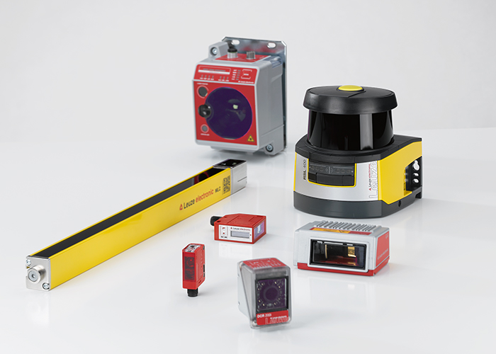
We offer devices with ex marking for different areas of application:
— CML 700 measuring light barriers
— MLC 500 safety light curtains
— Measuring sensors of the ODS series
— Switching sensors of the 46 series
— RFM 32 RFID solutions

[02] Position control of the SKID

Requirement:
The position of the SKID must be determined exactly so that the subsequent work steps can be coordinated and synchronized.

Solution:
Depending on the installation situation, inductive switches with cylindrical or cubic design are suitable. The robust devices of the IS 230 and IS / ISS 244 series are characterized by increased operating ranges and LED status indicators.

[03] Contour monitoring for type detection

Requirement:
For positioning and synchronization of the painting robot, the body model must be detected. The bodies differ, e.g., near the A- and B-pillars with respect to design and dimensions. These features are to be used for detection.

Solution:
The CML 700i measuring light curtains determine, e.g., the distances between the A- and B-pillars or the different widths of the window openings. The results of these measurements are used to determine the body types and, thus, to control and synchronize the painting robots.

[04] Access guarding in the paint booth

Requirement:
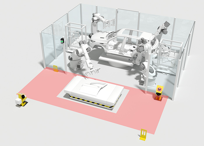
Access to the paint booth or to the CDC bath is to be guarded. At the same time, the safety sensor technology should allow the vehicle bodies to be transported into these areas and also function reliably if body formats are changed. In addition, the closed state of the pendulum flaps is to be monitored.

Solution:
The MLC 530 SPG safety light curtains with Smart Process Gating require no additional muting sensors for bridging for the transported goods. The space-saving solution guarantees high availability and high protection against manipulation. The partial gating simultaneously uses the upper beams of the safety light curtain to also monitor the pendulum flaps.

[05] Position control of the body

Requirement:
If different bodies are transported on a SKID and the work process requires the exact starting point of the body for purposes of synchronization, this must be detected contact-free.

Solution:
Our ODS 10 / HT 10 distance sensors in measuring or switching versions are ideal. They operate according to the principle of time-of-flight measurement (TOF) and, with an operating range of 8 m, are very well suited for applications over larger distances.

[06] Guarding and navigation of automated guided vehicles (AGVs)

Requirement:
The transportation path of the AGV must be guarded by means of safety sensors. The protective fields are to be flexibly adapted to the movement and loading situation. If the principle of natural navigation is used, the device is at the same time to provide the measurement data for the navigation software.

Solution:
The RSL 400 safety laser scanners merge safety technology and high-quality measurement value output in a single device. They have a scanning range of 270° and 100 reversible field pairs. Two scanners therefore provide optimum guarding of the AGV. The measurement data has a high angular resolution of 0.1° and a low measurement error.

[07] Identification of SKID and body

Requirement:
The SKID or the body must be identified so that process parameters, such as paint application in the paint booth, can be correctly set. The data carrier must withstand temperatures of 200°C here.

Solution:
The RFID systems of the RFM series operate in the 13.56 MHz frequency band and are available with various antennas depending on the required operating range. Transponders with different geometries and special, paint-compatible, high-temperature transporters are available for temperatures up to 250°C that match the frequency band.

[08] Code reading on attachment parts

Requirement:
If accessory parts and attachment parts did not pass through the painting process together, they must be identified for proper assignment.

Solution:
The DCR 200i camera-based code readers can be flexibly integrated thanks to their compact housing. For especially large reading distances with the same high depth of field, the BCL 500i bar code readers are used.

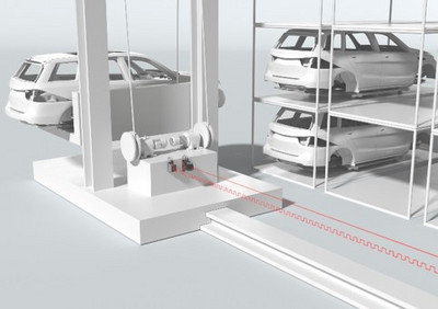
[09] Applications in the body warehouse

Requirement:
Automated buffer storages in the paint shop have requirements on the sensor system that are similar to those in the body shop. Examples are the determination of position data in the travel/lifting area and the optical transmission of this data. Compartment occupation checks and presence control of the skid in the lifter are typical applications.

Solution:
The positioning of the x/y axis is realized with the AMS 300i laser distance measurement system. The DDLS 500i data transmission photoelectric sensors are available for optical data transmission of up to 100 Mbit and distances of up to 200 m; sensors of the 10 series are available for compartment occupation checks. Inductive switches perform the presence testing.

[10] Error-free acceptance of the blanks

Requirement:
The vacuum gripper on the robot arm automatically removes the top-most part from the stacked blanks and places it on the conveyor system of the press line. To avoid errors in the work process, the length of the blank must be used to determine whether the part located underneath is lifted up as well – e.g., through adhesion.

Solution:
The CSL switching light barriers monitor the entire surface of the blank. Depending on requirements, the devices are available in various lengths and resolutions. The combination of integrated IO-Link interface and freely programmable switching outputs ensures simple integration in the system.

[11] Monitoring of the stack height

Requirement:
During operation, a continuous material infeed must be ensured. If the last blank is gripped by the robot or the filling level of the blank stack drops below a defined level, resupply is to be triggered automatically. To do this, the stack height of the blanks is to be monitored.

Solution:
A wide range of switching or measuring distance sensors is available. A good choice is the HT 10 as switching sensor, which monitors a defined stack height to ensure it does not drop below a defined level. Or the ODS 10 as measuring sensor for determining the stack height. Both use the time of flight measurement (ToF) for the required operating range. Of course, the right cables, fastening and mounting accessories are also available.

[12] Presence control for controlling the gripper robot

Requirement:
At the end of the press line, the finished molded sheet metal parts are automatically removed and loaded on transport vehicles for further processing. To control the gripper robot, the presence of the parts on the belt conveyor must be checked.

Solution:
The HT 25 C series from the broad product range of switching sensors is suitable. Both glossy as well as dark parts are reliably detected. Alternatively, red or infrared models are available.

[13] Code reading on the rack

Requirement:
The finished sheet metal parts are stored on movable racks that can be transported, e.g., by automatic tugger trains or AGVs, to the further processing in the body shop. To ensure that the rack is used correctly, the code attached to the rack that is to be read for identification.

Solution:
Depending on the attachment of the code and the reading distance, a BCL 300i decodes the code as a raster scanner and transfers the data to the PLC or to the material flow computer. If the label has large position tolerances, device models with integrated oscillating mirror are used.