The press shop

From the steel coil to the car.

Various body parts for the subsequent finished vehicles are produced from massive steel rolls, so-called coils.

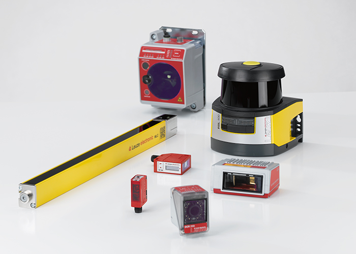
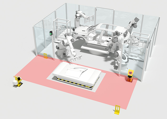
Whether for cutting the coils or punching, pressing and shaping the blanks: sensors accompany and safeguard all manufacturing steps, even under harsh environmental conditions.

The applications are as diverse as our product range, which is tailored to these applications. Inductive and optical sensors check and monitor the presence and position of parts. Identification systems record data for the traceability of those parts. At the cutting systems, our sensors supply measurement values for loop control and edge control.
[01] Code reading on the steel coil

Requirement:
The relevant technical data, such as material and material thickness, are encoded onto the coil. After removing the coils from the warehouse and before they are accepted into the cutting machine, this data must be recorded in order to ensure traceability over the entire process chain.

Solution:
The DCR 200i camera-based code readers read all common 1D- and 2D-codes, are easy to configure, and, thanks to the various optics, are simple to install. In cases where the position of the 1D-code on the coil can vary, the oscillating mirror model of the BCL 300i bar code reader is used.

[02] Area guarding of the feeder

Requirement:
The extremely heavy coils are fed into the cutting system by means of forklift trucks or AGVs. Access to the area near the feeder of the cutting machine must be safeguarded.

Solution:
The MLC 500 safety light curtains are available in numerous protective field lengths and resolutions and, through short safety distances, support a compact system design. If there is sufficient space, the MLD 500 multiple light beam safety devices are used as an alternative. These are also optionally available with integrated muting functions.

[03] Measuring the coil diameter

Requirement:
To enable an automatic coil change before the material runs out, the diameter of the coil must be constantly monitored. Cost-intensive downtime can thereby be minimized.

Solution:
The measuring ultrasonic sensors of the DMU 300 / 400 series offer an especially large measurement range of up to 6,000 mm. The robust devices in plastic and full-metal versions are characterized by short response times and high resolutions. They are available with analog current or voltage output and IO-Link interface.

[04] Loop control

Requirement:
In the cutting system, the cutting process must be decoupled from the belt transport. The sag of the loop is to be determined contact-free to communicate the necessary measurement values to the control for determining the haul-off speed.

Solution:
The sensors of the ODS10 / 110 and ODSL 96 series, which operate according to the time-of-flight measurement principle (TOF), offer measurement ranges of several meters. They feature a high resolution and a high level of reproducibility. The devices can be flexibly integrated via analog output, serial interface and IO-Link. 

[05] Edge control

Requirement:
The blank cutting system cuts the material that is unwound from the endless band into so-called plates or blanks. To ensure that they are identical in shape and dimensions and within tolerance, the edge must be precisely controlled.

Solution:
With their high level of reproducibility of ± 0.03 mm, the GS 754B CCD fork photoelectric sensors ensure precise determination of the web edge. The devices can be flexibly integrated via analog output, serial interface or IO-Link.

[06] Anteroom guarding on press lines

Requirement:
Before the carriages move into the press, a check must be performed to ensure that no persons are in front of the gates. During entry, the area to the side of the carriages is to be secured to prevent persons from entering the press line alongside a carriage.

Solution:
With its configurable and switchable protective fields, the RSL 400 safety laser scanner secures the area in front of the respective door. With its large operating range of 8.25 m and two parallel protective functions, two entrance areas can be simultaneously monitored independent of one another with just one device.

[07] Access guarding on press lines

Requirement:
The press tools are bought to the press anteroom with gantry cranes and positioned in the press during a tool change. During this process, the entire anteroom is a safety-critical area. The access of persons must be monitored.

Solution:
The multiple light beam safety devices of the MLD 500 series offer economical access guarding for large areas. As transmitter-receiver systems with operating ranges of 70 m, they are used together with mirror columns and thereby safeguard the entire press anteroom.

[08] Presence control of the tool

Requirement:
The fitting tool is positioned on the shuttle carriage by means of a crane. In doing so, the proper seating is to be checked so that automatic locking can occur.

Solution:
The IS / ISS 244 models with cubic design are the best suited from our wide range of inductive switches. The compact sensors can be installed quickly and in a space-saving manner. Status indicators that are easily visible from the side simplify commissioning and visualize states.

[09] Position control of the pallet

Requirement:
The cut, in some cases, already stamped blanks are fed for further processing by means of forklift trucks or automated guided vehicles. Before the parts can be accepted, a check must be performed to ensure that the pallet or load carrier has reached the transfer position. This is to occur contactlessly.

Solution:
The inductive switches of the IS 200 / 244 series offer high performance and large function reserve. Depending on the installation location and the required operating range, both cylindrical designs with triple switching distance from the IS 200 series as well as the IS / ISS 244 cubic versions are available.

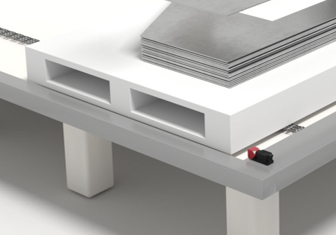
[10] Monitoring of the stack height

Requirement:
During operation, a continuous material infeed must be ensured. If the last blank is gripped by the robot or the filling level of the blank stack drops below a defined level, resupply is to be triggered automatically. To do this, the stack height of the blanks is to be monitored.

Solution:
Devices with time-of-flight measurement (TOF) from our wide range of switching and measuring distance sensors are especially well suited for larger operating ranges. These include the HT 10 switching sensors, which monitor a defined stack height to ensure that it does not drop below a defined level, and the ODS 10 measuring sensors, which determine the height of the stack.

[11] Error-free acceptance of the blanks

Requirement:
The vacuum gripper on the robot arm automatically removes the top-most part from the stacked blanks and places it on the conveyor system of the press line. To avoid errors in the process, the entire length of the blank must be used to determine whether the part located underneath is lifted up as well – e.g., through adhesion.

Solution:
The CSL 700 switching light barriers monitor the entire surface of the blank. Depending on requirements, the devices are available in various lengths and resolutions. The combination of integrated IO-Link interface and freely programmable switching outputs ensures simple integration in the system.

[12] Presence control for controlling the gripper robot

Requirement:
At the end of the press line, the finished molded sheet metal parts are automatically removed and loaded on transport vehicles for further processing. To control the gripper robot, the presence of the parts on the belt conveyor must be checked.

Solution:
From our wide product range of switching sensors, the HT 25C series combines above-average function reserve with compact size. Parts with glossy and even dark or structured surface are reliably detected. The devices are available as red light and infrared versions.

[13] Code reading on the rack

Requirement:
The finished sheet metal parts are stored on movable racks that can be transported, e.g., by automatic tugger trains or AGVs, to the further processing in the body shop. To ensure that the rack is used correctly, the identification code attached to the rack that is to be read.

Solution:
Depending on the attachment of the code and the reading distance, a BCL 300i decodes the code as a raster scanner and transfers the data to the PLC or to the material flow computer. If the label has large position tolerances, device models with integrated oscillating mirror are used.