Guards
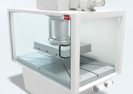
Hard guards prevent access to danger zones and at the same time also protect (depending on the model) against projected (thrown out) objects and (depending on the model) against dangerous emissions from the machine. ISO 12100 and ISO 14120 contain normative requirements with regard to their design. Extracts of the most important requirements are listed in the following sections.
The height of protective fences, openings and mesh sizes of wire screens must be dimensioned in accordance with ISO 13857 or applicable C-standards and far enough away from the point of operation such that it cannot be reached by any part of the body.
|
|
|
| |
| Type of protective device |
Fixed guard (e.g. fences or covers) |
Moving guard (e.g. doors or flaps) Monitoring through interlock devices without guard interlocking (safety switches) |
Moving guard (e.g. doors or flaps) Monitoring through interlock devices with guard interlocking (safety locking devices) |
| Application examples | Long lifetime, protection against injury caused by projected (thrown out) parts, objects. | Access to machine is possible. Safety doors cannot be opened or removed undetected. | The safety door can only be opened with an electric unlocking signal. No safety distance required. |
Fixed guards – hard guard
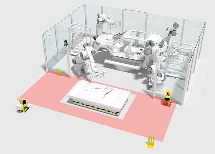
Fixed guards, e.g. hard guards, barriers or fixed covers, can be used wherever access to the danger zone is not required during normal operation. These include protective fences, barriers, fixed covers, etc. Fixed guards are also frequently used in combination with optoelectronic protective devices as supplementary protective devices.
ISO 12100 requires that fixed guards must be firmly held in their place with constructive measures:
- either permanently (e.g. welded)
- or with fixing elements (nuts, bolts) that require the use of a tool. If possible, it should not be possible to keep them in the protective position after the fixing elements have been loosened.
- or position-monitored with control-connected safety switches (ISO 14119) so that all relevant dangerous movements are stopped with the removal of the protective device.
ISO 13857 contains two tables for dimensioning the height and required safety distance of fixed hard guard protective devices in accordance with the height of the point of operation. The table contains measurement recommendations for applications with high risk.
ISO 14120 contains general information on implementing fixed guards.
Moving guards
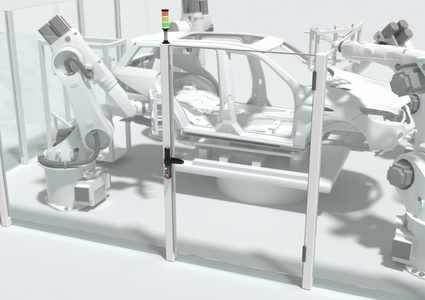
If access to the danger zone is required during normal operation or relatively frequently for maintenance work, moving guards such as safety doors or flaps can be used.
A moving guard provides protection only in its closed position. If it is opened, access to the point of operation is unobstructed and the protective device loses its inhibiting protective function. The position of a moving guard therefore requires reliable monitoring. If it is opened, all hazardous events (e.g. dangerous movements) must be rendered ineffective. To this end, interlock devices are used which reliably detect or prevent a moving guard from opening, usually by means of an electrical control circuit.
ISO 14119 makes a distinction between two types of interlock devices:
- Without guard interlocking – commonly referred to as "safety position switches", or "safety switches" for short. When actuated, they deliver a safe shutdown signal to the control, but do not prevent the guard from opening
- With guard interlocking – commonly referred to as "door locks". They also deliver a safe shutdown signal to the control, but by means of a mechanical or magnetic locking device additionally prevent the guard from being opened for as long as no release is given by the control.
Interlock devices must always be set up so that they cannot be easily manipulated. To assess the interlock devices, ISO 14119 divides them into types:
| Type | Actuation | Actuator | Leuze product | ||
| Operating principle | by | Encoding | Example |
| |
| Type 1 | Mechanical | Contact, forced | Not encoded | Cam disk | S300 |
| Control cam | - | ||||
| Hinge | S400 | ||||
| Type 2 | Encoded | Switching tongue Specially shaped actuator | S20, S200, L10, L100, L200 | ||
| Key | - | ||||
| Type 3 | Contactless | Inductive | Not encoded | Ferromagnetic materials | - |
| Magnetic | Electromagnet/solenoid | - | |||
| Capacitive | All suitable materials | - | |||
| Ultrasonics | All suitable materials | - | |||
| Optical | All suitable materials | - | |||
| Type 4 | Magnetic | Encoded | Encoded solenoid | MC 300 | |
| RFID | RFID transponders | RD 800, L250, L300 | |||
| Optical | Optically encoded actuator | - | |||
Series connection of contacts
Contacts of interlock devices that belong to the same safety function can be connected in series. If in this case only one of the switches opens, the associated safety function executes its safe reaction, usually the stopping of movements. The apparent poorer diagnostic capability is demonstrated by the fact that it is not possible to tell which of the series-connected guards was actuated. This is additionally reflected in the diagnostic coverage DC owing to the so-called fault masking of contacts. ISO 14119 formalizes this fact in Technical Report ISO/TR 24119 as follows:
| Number of frequently used protective devices 1), 2) | Number of frequently used protective devices 3) | Maximum achievable diagnostic coverage DC |
| 0 | 2 ... 4 | Medium (90%) |
| 5 ... 30 | Low (60%) | |
| > 30 | None (0%) | |
| 1 | 1 | Medium (90%) |
| 2 ... 4 | Low (60%) | |
| > 4 | None (0%) | |
| > 1 | ≥ 0 | None (0%) |
1) Frequently = The protective device is actuated at least once per hour
2) Every additional operator increases the number of frequently used protective devices by 1
3) The number of additionally used protective devices can be reduced by 1 if the distance between them is greater than 5 m or none of the additional protective devices can be reached directly.
DC = 99% and therefore PL e can only be achieved with individual connection of a contact-based sensor to the evaluation logic.
Interlock devices without guard interlocking (safety switches)
Interlock devices without guard interlocking are used for position monitoring of safety doors or flaps, for example. The movable guard can be opened at any time. As soon as the moving guard is no longer closed, a stop command is generated by the safety switch. For e.g. a dangerous movement to be brought to a standstill in good time before the point of operation is reached, a suitable safety distance between the protective device and point of operation must be observed.
If a C-standard or other machine-specific regulations are not available, the required safety distance S can be determined as follows:
- Safety distance of the closed protective device in accordance with ISO 13857 for fixed guards as given in a table
- Safety distance of the moving guard (open) in accordance with the calculation formula given in ISO 13855:
| S = (K * T) + C | |
| S | Minimum distance in millimeters, measured from the danger zone to the guard |
| K | 1600 mm/s approach speed of a person's body or parts of the body |
| T | Run-on of the entire system in seconds |
| C | Additional distance (taken from table 4 of ISO 13857 if it is possible to insert fingers or hands through the opening in the direction of the danger zone before a stop signal is produced.) |
The greater of the two values is the necessary safety distance of the protective device.
Interlock devices with guard interlocking (safety locking devices)
Interlock devices with guard interlocking keep the guard in a closed position. They are always used when the dangerous machine function has not ended after the protective device has been opened, before a person can reach the point of operation (e.g. with long machine stopping times). With the guard interlocking the guard stays closed until the dangerous state has ended. If the operator wants to open the protective device, he must request this by actuating a button at the control. The control then stops the machine and unlocks the locking device. A further application area is machine protection. Safety locking devices are frequently also used when undefined interruptions of the production process are to be prevented for process safety reasons (see also, IEC 60204‑1, 9.3).
ISO 14119, 4.3.2 differentiates between the types of technical execution of the locking device (actuated = locked):
1. Actuated manually and locked manually
2. Actuated by spring force and unlocked by energy (e.g. electrical signal)
3. Actuated by energy (e.g. using electromagnet) and unlocked by spring force
4. Actuated by energy and unlocked by energy
Safety locking devices with spring force-actuated interlocking (2.) also remain interlocked with a power failure on the entire machine and therefore keep a safety door blocked, including during the machine's stopping time. Because of this property they are preferred over the power-actuated (magnetic-force actuation) Safety Locking Devices for people protection applications. Locking devices actuated by magnetic force are not usually used for personnel protection, but rather for machine protection.
Unlocking of a safety locking device
The safety level of the locking function must not be impaired by a non-safety-related locking function (ISO 14119, 5.7.1.). The unlocking of a locking device must be described in addition to the locking function by means of a separate safety function to which, according to ISO 14119, 8.4, the following elements belong:
- Position monitoring of the locking device
- Identification of the conditions for unlocking (e.g. rotational speed or position monitoring, time delay)
- Logic for evaluation of these signals
- Actuation for unlocking the locking device
The "Actuation of locking device" safety function must have at least the PLr determined by means of a risk assessment. Here, however, only the short period
- between the rare event "Incorrect actuation of locking device due to failure of a control component" (read-back of the solenoid position should initiate a machine stop)
- and "Non-conformant opening of protective device between incorrect actuation and stopping of dangerous movements"
needs to be considered for the risk assessment. This probability is generally extremely low so that usually no high demands with respect to the PLr are placed on the actuation of the locking device.
Additional unlocking of the locking device
Escape unlocking
The escape unlocking function is used for manual unlocking of the locking device from inside the danger zone in order to then leave the danger zone. The actuator for escape unlocking may therefore only be accessible within the danger zone and it must be possible to actuate it manually. Triggering of the escape unlocking leads to a stop command being sent to the machine control.

Example of an escape unlocking button on the L300 safety locking device
Emergency unlocking
The emergency unlocking function is used for manual unlocking of the locking device from outside the danger zone in an emergency. It must be possible to actuate the emergency unlocking actuator manually. Triggering of this function leads to a stop command being sent to the machine control and to blocking of the locking element, which can only be reset using tools or by means of a special actuation or requires the component to be replaced.
Auxiliary release
Auxiliary release from outside the danger zone must only be possible using a tool or a key. It provides the possibility of manually unlocking the locking device from outside the protected area, e.g. in the event of a malfunction. Triggering of this function must lead to a stop command being sent to the machine control. Resetting is only possible using tools or by means of a special actuation.
The auxiliary release function is not suitable for emergency unlocking or escape unlocking of the locking device.

Example of an auxiliary release, which can only be opened using tools, on the L300 safety locking device





.jpg)
