


垂直(直角)接近
EN ISO 13855:2010に準拠した計算ウィザード
このウィザードによる推奨事項は、完全性を保証するものではありません。本製品の安全かつ適切な使用および設置には、現在有効なバージョンの関連規格および規則に従う必要があります。Leuze electronic GmbH + Co. KGは、本ウィザードの使用によって生じる損害、または一般的に適用される規格および指令の精度について、一切の責任を負いません。
垂直接近かつ分解能が40mm以下の場合における最短距離の算出
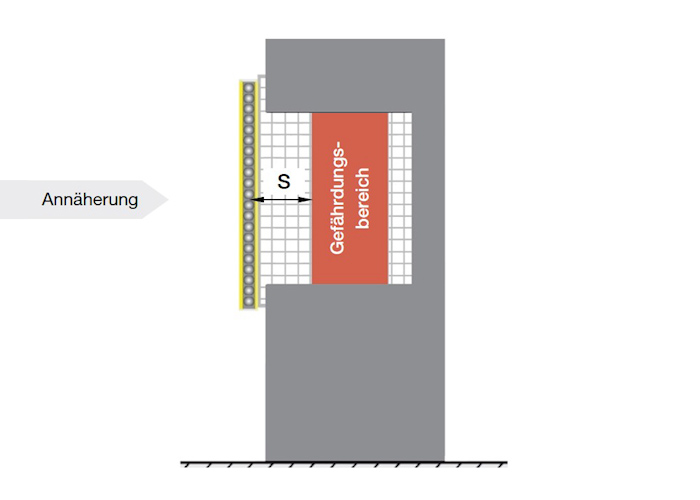 |
最短距離SRTは、以下の式で計算されます: SRT - - 防護領域と動作点間の最短距離 |
注意:また、重なりが可能な場合は、CRO (重なり)による表の値を決定する必要があります。CROがCRT よりも大きい場合、CRT の代わりにCROの値を使用して最短距離を決定する必要があります。
最初に、Kの値に2.0 mm/msを使用して計算を行います。計算結果SRTが500mmを超える場合は、K=1.6mm/msとして計算を再度行っても構いません。第2ステップでSRTの結果は500mm以上でなければなりません(計算値が低い場合、SRTは500mmに設定されます)。
注意:操作点までの距離Sは、たとえ計算値値が下回ったとしても、常に少なくとも100 mmである必要があります。
垂直接近かつ分解能が40mm以上の場合における最短距離の算出
注意:この式は、マルチライトビーム安全装置、セーフティライトカーテン、セーフティ・レーザースキャナに対応する分解能で適用されます。
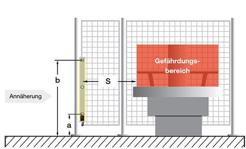 |
最短距離SRTは以下の式で計算されます: SRT-防護領域と動作点間の最短距離 K- 接近速度:1.6 mm/ms |
S:最短距離
a:基準面からの下端ビームの高さ
b:基準面からの上端ビームの高さ
注意:CRO(乗り越え接近)の表の値も決定する必要があります。原則として、この値が850mmを上回る場合は、計算式の850mmの代わりにこの値を使用する必要があります。
|
|
|
|||||||||||
|
危険 |
感電保護具の保護領域上端の高さ |
|||||||||||
| 900 | 1 000 | 1 100 | 1 200 | 1 300 | 1 400 | 1 600 | 1 800 | 2 000 | 2 200 | 2 400 | 2 600 | |
|
危険領域までの追加距離 CRO |
||||||||||||
| 2 600 | 0 | 0 | 0 | 0 | 0 | 0 | 0 | 0 | 0 | 0 | 0 | 0 |
| 2 500 | 400 | 400 | 350 |
300 |
300 | 300 | 300 | 300 | 250 | 150 | 100 | 0 |
| 2 400 | 550 | 550 | 550 | 500 | 450 | 450 | 400 | 400 | 300 | 250 | 100 | 0 |
| 2 200 | 800 | 750 | 750 | 700 | 650 | 650 | 600 | 550 | 400 | 250 | 0 | 0 |
| 2 000 | 950 | 950 | 850 | 850 | 800 | 750 | 700 | 550 | 400 | 0 | 0 | 0 |
| 1 800 | 1 100 | 1 100 | 950 | 950 | 850 | 800 | 750 | 550 | 0 | 0 | 0 | 0 |
| 1 600 | 1 150 | 1 150 | 1 100 | 1 000 | 900 | 850 | 750 | 450 | 0 | 0 | 0 | 0 |
| 1 400 | 1 200 | 1 200 | 1 100 | 1 000 | 900 | 850 | 650 | 0 | 0 | 0 | 0 | 0 |
| 1 200 | 1 200 | 1 200 | 1 100 | 1 000 | 850 | 800 | 0 | 0 | 0 | 0 | 0 | 0 |
| 1 000 | 1 200 | 1 150 | 1 050 | 950 | 750 | 700 | 0 | 0 | 0 | 0 | 0 | 0 |
| 800 | 1 150 | 1 050 | 950 | 800 | 500 | 450 | 0 | 0 | 0 | 0 | 0 | 0 |
| 600 | 1 050 | 950 | 750 | 550 | 0 | 0 | 0 | 0 | 0 | 0 | 0 | 0 |
| 400 | 900 | 700 | 0 | 0 | 0 | 0 | 0 | 0 | 0 | 0 | 0 | 0 |
| 200 | 600 | 0 | 0 | 0 | 0 | 0 | 0 | 0 | 0 | 0 | 0 | 0 |
| 0 | 0 | 0 | 0 | 0 | 0 | 0 | 0 | 0 | 0 | 0 | 0 | 0 |